IBM V7000 Expansion Canisters Hardware Overview explained
As the below figure shows, two 12 Gbps SAS ports are side by side on the canister of every enclosure. They are numbered 1 on the left and 2 on the right. Similarly to the controller canisters, also expansion canisters are installed in the enclosure side-by-side in vertical position. In this Article we are going to see IBM V7000 Expansion Canisters Hardware Overview Explained.
Brief Description on IBM V7000 Expansion Canisters:
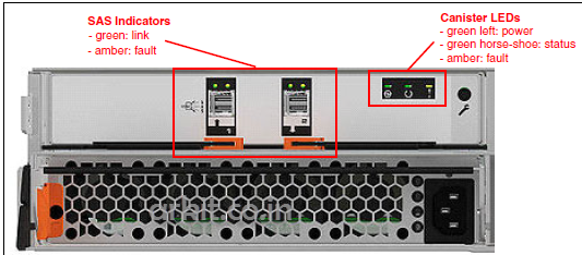
Expansion-canister
The interpretation of SAS status LED indicators has the same meaning as the LED indicators of SAS ports in control enclosure
SAS-LED’s-status
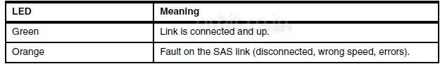
The below table shows the LED status values of the expansion canister.

Expansion-Canister-LED’s-status
Enclosure SAS Cabling
Expansion enclosures are attached to control enclosures using 12 Gbps SAS cables. IBM Storwize V7000 Gen2 Control Enclosure attaches up to 20 expansion enclosures – twice more than the previous generation.
A strand starts with an SAS initiator chip inside an IBM Storwize V7000 node canister and progresses through SAS expanders (Card), which connect disk drives; each canister contains an expander. The below shows how the SAS connectivity works inside the node and expansion canisters. Each drive has two ports, each connected to a different expander and strand. This configuration assures that both nodes in the I/O group have direct access to each drive and there is no single point of failure.
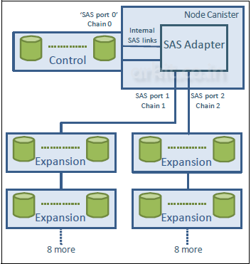
Concept-of-SAS-chaining
A chain consists of a set of enclosures, correctly interconnected it has shown in below figure. Chain 1 of an I/O group is connected to SAS port 1 of both node canisters; chain 2 is connected to SAS port 2. This configuration means that chain 2 includes the SAS expander and drives of the control enclosure.
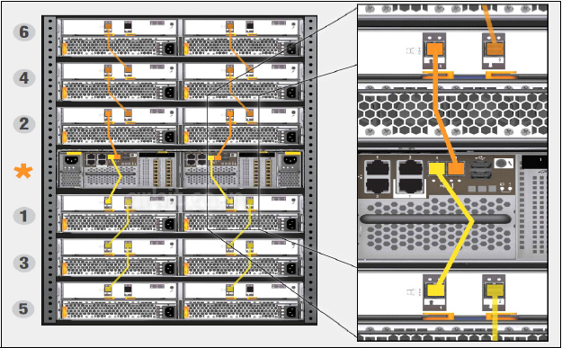
SAS-Cabling-with-number-of-enclosures
At system initialization, when devices are added to or removed from strands, IBM Storwize V7000 performs discovery process to update the state of the drive and enclosure objects.
IBM V7000 Power Units:
All enclosures accommodate two power supply units (PSU) for normal operation. A single PSU can supply the entire enclosure for redundancy. For this reasons is highly recommended to supply AC power to each PSU from different power distribution unit (PDU).
There is a power switch on the power supply and indicator LED’s. The switch must be on for the PSU to be operational. If the power switch is turned off, then the PSU stops providing power to the system. For control enclosure PSU’s, the battery integrated in the node canister continues to supply power to the node.
Fully charged battery is able to perform two firehose dumps. It supports the power outage 5 seconds before initiating safety procedures.
The below figure shows two PSU present in the control and expansion enclosure. The controller PSU has two green and one amber indication LED’s reporting the status of PSU.

Controller-and-expansion-enclosure-led-status-indicator
The below figure represents the rear overview of the enclosure canister with power unit (PSU). In contrast to he control enclosure, these PSUs do not have power switch. The enclosure is powered on by direct attachment of power cable.
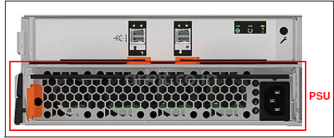
Expansion-enclosure-power-supply-unit
Power supplies in both control and expansion enclosures are hot-swappable and replaceable without a need to shutdown a node or cluster. If the power is interrupted in one node for less than 5 seconds, the canister will not perform firehose dump and continue operation from battery.
This is useful for a case of for example maintenance of UPS systems in the data center or re plugging the power to the different power source or PDU unit. A fully charged battery is able to perform two firehose dumps.
That’s about IBM V7000 Expansion Canisters Overview
Related Articles
Download Configuration Backup V7000 Storage
How to Replace Hardware IBM Storage
Thanks for your wonderful Support and Encouragement